SUD40IX-V12
| □ Specification |
| MODEL |
SUD□IA-V12 |
SUD□IB-V12 |
SUD□IC-V12 |
SUD□ID-V12 |
SUD□IX-V12 |
| Rated Voltage |
1ø 110V 60Hz |
1ø 220V 60Hz |
1ø 100V 50/60Hz |
1ø 200V 50/60Hz |
1ø 240V 50Hz |
|
Output
|
6W |
SUD06IA-V12 |
SUD06IB-V12 |
SUD06IC-V12 |
SUD06ID-V12 |
SUD06IX-V12 |
| 15W |
SUD15IA-V12 |
SUD15IB-V12 |
SUD15IC-V12 |
SUD15ID-V12 |
SUD15IX-V12 |
| 25W |
SUD25IA-V12 |
SUD25IB-V12 |
SUD25IC-V12 |
SUD25ID-V12 |
SUD25IX-V12 |
| 40W |
SUD40IA-V12 |
SUD40IB-V12 |
SUD40IC-V12 |
SUD40ID-V12 |
SUD40IX-V12 |
| 60W |
SUD60IA-V12 |
SUD60IB-V12 |
SUD60IC-V12 |
SUD60ID-V12 |
SUD60IX-V12 |
| 90W |
SUD90IA-V12 |
SUD90IB-V12 |
SUD90IC-V12 |
SUD90ID-V12 |
SUD90IX-V12 |
| 180W |
SUD180IA-V12 |
SUD180IB-V12 |
SUD180IC-V12 |
SUD180ID-V12 |
– |
|
Operation Voltage Range
|
± 10 %(standard) |
|
Speed control range
|
60Hz : 90 ~ 1700 rpm 50Hz : 90 ~ 1400 rpm |
|
Speed variation
|
5%(standard) |
|
Speed setting device
|
Digital setting |
|
SLOW RUN
SLOW STOP
|
possible |
|
Temperature limits for use
|
0 ~ 40 ℃ |
|
Temperature limits for storage
|
-10 ~ 60 ℃ |
|
Humidity limits
|
Less that 85% RH (Non condensing) |
|
| □ Functions of Difiral Type Speed Controller |
|
◎ The following functions are features of the automatic computer control.
| Functions |
Descriptions |
| Rotary Direction Alternating Function |
Clockwise/Counterclockwise Terminals |
| Run/Stop |
Set bye the RUN/STOP key |
| Revolving Speed Setup |
Disital setup (Multiplication by a unit of 10rpm) |
| Indication Magnification Setup |
Setup for Gear deceleration ratio (refer to the chart) and Multiple magnification (units of 0.005) |
| SLOW RUN SLOW STOP |
0.1sec. ~ 30sec. (unit of 0.1sec.) |
| Setup in Powered-on Status |
Setup for the power source status as the power is supplied |
| Locking Function |
Prevention of Incorrect Operation |
| Setup Parameters |
Setup for powering off and saving the parameters. |
|
|
|
|
| □ How to Use Correctly |
|
(1) POWER-ON Status Alternating Switch (default setting is “NO”)
This model features the following two modes to select the running status of mnotor, when power is supplied. |
|
| YES |
If the status is set to “RUN” before being powered off, it runs even though the power is supplied.
If the status is set to “STOP” before being powered off, it stops even though the power is supplied. |
| NO |
Regardless of the status before being powered off, whether it might be “RUN” or “STOP”, it stops when the power is supplied. |
|
| ㆍPlease setup as “NO” before ordinary use. It may helpp prevent an unexpected operation incurred by restoration after blackout or when power is suppied again. |
| When using it set to “YES” |
|
(Please use in the SET mode) |
|
| It is possible to remotely control its running or stopping by manipulating the RUN/STOP key as it is powered “on” or “off”. |
|
|
1. Please set the Power-on Status Alternating Switch as “YES”.
2. Please click the RUN/STOP key once as the power is supplied.(To make sure the perception of the operation of “YES”. |
|
|
|
1. It takes about 2 seconds of resetting time from power being supplied until the commencement of operation.
2. The operation can be delayed when it is used for extended period of time with the RUN/STOP key. Then, it indicates “RUN” and “STOP” simultaneously. When this occures, the operation can be restored to normal condition by alternating to “NO”, turning it off for more than 1 second, and restoring the power supply, provided that the function of “YES” is still available. |
|
(2) Restoration after a blackout
The operation depends on the selected status prior to the blackout by the Power-on Status Alternating Switch in cases such as to detect an instant blackout or to restore the power supply. |
(3) RESET Time
It requres about 2 seconds of resetting time when the power is supplied. And in this period, no digital indication is made. |
 |
| After the power is supplied, please use the keys to change the status after the digital indications are completely made. And if the status is set to “RUN” before turning it off when the Power-on Status Alternating Switch is set as “YES”, it stats the operation about 2 seconds after the power is supplied. It also takes about 2 seconds in the case of an instant blackout. |
(4) Automatic alternation of frequency.
Set as 1400 ~ 1800rpm (multiplication ration of 1) in the region of 60Hz, it becomes 1500rpm in the region of 50Hz. Set as 1500rpm in the region of 50Hz, howere, it remains 1500rpm even in the region of 60Hz. |
(5) Trouble indications.
When any trouble occure, “RUN” and “STOP” are simultanously indicated. Some cases show that it may be restored to the normal condition when the power is supplied again (provided that the setting values become the default ones). If it simultaneously indicates “RUN” and “STOP” even after the power is restored, you must consider a malfunctions of the internal circuits. Please inform the technology institute of the company. If the operation lifespan of the RUN/STOP key expires withe the Power-on Status Alternating Switch set to “YES”, please refer to the countermeasures of Clause 7.1. |
(6) THERMAL PROTECTOR(Automatic Return Type)
As protection against overheating, a thermal protector is built into the motor, according to the type of the motor. As the motor becomes overheated, the thermal protector is actuated to stop the operation. And when the motor is cooled later, the thermal portector returns, and it runs again without manipulation for “RUN”. |
(7) Tests on dielectric strength and impulse voltage.
On the power plug, please cut off the two wires outside of the motor ground wire for performing test on dielectric strength between the line earths, on impulse internal pressure, and on insulation resistance, as it is installed on the control plate. |
|
|
|
|
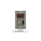
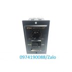
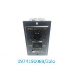
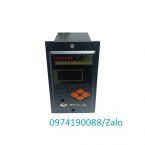
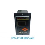
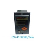
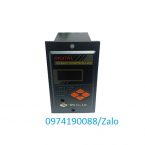
| □ Parts names and Functions |
 |
| □ Usage |
|
(1) Selection of rotary direction |
|
 |
1)For continuous one-way operation
ㆍTo reverse the rotary direction at conveying parts such as the gear head, please change the connections so that the positions of the connectors ⑤ COM and ④ CW attached to the side fo the controller are connected to ⑤ COM and ⑥ CCW.
ㆍPlease be sure that the power wires are connected to ①AC and ②AC in any case. for this, please turn it off before changing and connecting the wires. |
2)For clockwise and counterclockwise operation
ㆍPlease install the switches for power supply (SW1) and for changing the rotary directions (SW2) to change the direction of revolution.ㆍInstant direction-changing revolution is impossible. Please turn off the switch for power supply (SW1) first, and then exchange the switch (SW2) after the motor is stopped completely. |
| SWITCH No. |
SWITCH Contact Capacity |
| SW1 |
AC 125V or AC 250V, more than 5A |
| SW2 |
AC 125V or AC 250V, more than 5A |
|
| (2) Mounting Procedure |
 |
1) Make a rectangular hole on the mounting panel.
2) Insert the controleer body combined withe the front cover into the rectangular hole and use M4 screws and nuts to fix. |
|
|
|
|
| □ Discriptions of Operation Modes |
|
(1) RATIO MODE
This mode indicates the actual speed by multiplying the revolution speed by the magnification, where it is possible to calculate the revolution speed of the output axis of the gear head and the returning speed of the conveyor belt.
1) Set value of Gear Ratio (for indication donforming to the revolution speed of the output axis of the gear head)
<indicated value of “SER” or “REAL” = Revolution speed of motor ÷ Set value of gear ratio>
ex); since the default gear ratio of the Company is in memory, please use the ↑ and ↓ keys for selection.
1.000 ↔ 3 ↔ … ↔ 100… ↔ 202… ↔ 1000… ↔ 2515
Please refer to page 144: “6. Table of Gear Ration” |
2)Set value of Multiple Magnification (for indication conforming to the returning speed of the conveyor belt)
<indicated value of “SER” or “REAL” = Revolution speed of motor × Set value of multiple magnification>
ex) since the multiple magnification is set from 0.005 to 0.995, please use the ↑ and ↓ keys for selection.
1.000 ↔ 0.995 ↔ … ↔ 0.015 ↔ 0.010 ↔ 0.005 (intervals of 0.005) |
(2) SET MODE
This mode sets up the revolution speed, using the ↑ and ↓ keys. |
| If the indicated magnification is 1.000 |
The selection unit is 10rpm.
ex)ㆍPower frequency 50Hz : 90↔100↔110↔…↔1400↔1500rpm
ㆍPower frequency 60Hz : 90↔100↔110↔…↔1400↔1700↔1800rpm |
| If the indicated magnification is other than 1.000 |
It is indicated according to the indicated magnification setting in “RATIO MODE” and the gear ratio setting, which can be selected by using the ↑ and ↓ keys.
ex) Set value of gear ratio = 3
Selection with a unit of 10 ÷ 3rpm is possible. The value is indicated down to one decimal place.
ㆍPower frequency 50Hz : 29.9↔33.3↔36.6↔55.0↔…↔466.6↔500.0rpm
ㆍPower frequency 60Hz : 29.9↔33.3↔36.6↔55.0↔…↔466.6↔…↔566.6↔600.0rpm |
ex)Set value of multiple magnification = 0.500
Selection with a unit of 10 × 0.500rpm is possible. The value is indicated down to one decimal place.
ㆍPower frequency 50Hz : 45.0↔50.0↔55.0↔…↔700.0↔750.0rpm
ㆍPower frequency 60Hz : 45.0↔50.0↔55.0↔…↔700.0↔…↔850.0↔900.0rpm |
(3) REAL MODE
The REAL MODE indicates the actual revolution speed of motor by multiplying by the indicated magnification.
The selection unit in 5 rpm “for indicated magnification of 1.000.
ex) 0↔5↔10↔…↔90↔95↔100↔…↔1400↔…↔1700rpm
Indiates according to the indicated magnification setting of Ratio mode “for the indicated magnification is other than 1.000”. |
ex) Set value of gear ratio = 3
Selection with a unit of 5 ÷ 3 rpm is possible. The value is indicated down to one deciaml place.
0↔1.6↔…↔29.9↔31.6↔33.3↔…↔466.6↔…↔566.6 |
ex)Set value of multiple magnification = 0.500
Selection with a unit of 5 × 0.500rpm is possible. The value is indicated down to one decimal place.
0↔1.6↔…↔29.9↔31.6↔33.3↔…↔466.6↔…↔566.6rpm |
|
|
“rpm” is indicated only for the indicated magnifications exceeding 1.000 (including 1.000).
Noting is indicated when the indicated magnification is less than 1.000. |
|
(4) S/R MODE
This mode sets up the SLOW RUN time, using the ↑ and ↓ keys.
The selection unit is 0.1 second, of which the maximum range is to 30 seconds.
0↔0.1↔…↔0.2↔0.3↔0.4↔…↔29.9↔30.0 sec. |
(5) S/S MODE
This mode sets up the SLOW STOP time, using the ↑ and ↓ keys.
The selection unit is 0.1 second, of which the maximum rage is to 30 seconds.
0↔0.1↔…↔0.2↔0.3↔0.4↔…↔29.9↔30.0 sec. |
 |
(6) POWER-ON Status Setup MODE
As the Power-On Status Alternating Wsitch, this mode enables selections operation as the power is supplied.
1) If the mode is set as “YES”
When the power is supplied, it repeats the same operation as that before it was powered off. |
| Before being powered off |
After being powered on |
| “RUN” state |
Starting (about 2 sec. later) |
| “STOP”state |
Stop |
|
2) If the mode is set as “NO”
When the power is supplied, it is stop regardless of the previous state before being powered off. Please use RUN/STOP key for re-operation. |
| Before being powered off |
After being powered on |
| “RUN” state |
Stop |
| “STOP” state |
Stop |
|
|
|
|
|
| □ Table of Gear Ratios |
|
| Since there may be slight differences between the nominal bear ratios and the actual ones, please refer to the table for equipment setup. |
|
Norminal gear ratio
|
Actual gear ratio
|
Inter-decimal
GEAD HEAD
|
|
60甬 6W
|
70甬 15W
|
80甬 15W
|
80甬 25W
|
90甬 40W
|
90甬 60W
|
90甬 90W
|
|
3
|
3.00
|
3.00
|
3.00
|
3.00
|
3.00
|
3.00
|
3.00
|
10
|
|
3.6
|
3.60
|
3.59
|
3.57
|
3.57
|
3.60
|
3.60
|
3.60
|
|
5
|
5.00
|
5.00
|
5.00
|
5.00
|
5.00
|
5.04
|
5.04
|
|
6
|
6.00
|
6.00
|
6.00
|
6.00
|
6.03
|
6.00
|
6.00
|
|
7.5
|
7.50
|
7.50
|
7.50
|
7.50
|
7.50
|
7.50
|
7.50
|
|
9
|
9.00
|
9.00
|
9.00
|
9.00
|
9.00
|
9.00
|
9.00
|
|
10
|
10.00
|
10.29
|
10.00
|
10.00
|
10.00
|
10.00
|
10.00
|
|
12.5
|
12.50
|
12.14
|
12.50
|
12.50
|
12.50
|
12.50
|
12.50
|
|
15
|
15.00
|
15.00
|
15.00
|
15.00
|
15.00
|
15.00
|
15.00
|
|
18
|
18.00
|
17.92
|
18.08
|
18.08
|
17.67
|
18.00
|
18.00
|
|
20
|
19.90
|
20.00
|
20.00
|
20.00
|
20.00
|
20.19
|
20.19
|
|
25
|
25.06 |
24.80
|
25.00
|
25.00
|
24.73
|
25.00
|
25.00
|
|
30
|
30.25
|
30.00
|
30.00
|
30.00
|
30.00
|
30.00
|
30.00
|
|
36
|
36.30
|
36.00
|
36.00
|
36.00
|
36.00
|
36.00
|
36.00
|
|
40
|
40.80
|
40.36
|
40.11
|
40.11
|
40.36
|
39.68
|
39.68
|
|
50
|
50.00
|
50.00
|
50.00
|
50.00
|
50.00
|
50.00
|
50.00
|
|
60
|
60.00
|
60.00
|
60.00
|
60.00
|
60.00
|
60.00
|
60.00
|
|
75
|
75.00
|
75.00
|
75.00
|
75.00
|
75.00
|
76.02
|
76.02
|
|
90
|
90.00
|
90.67
|
90.00
|
90.00
|
90.00
|
90.00
|
90.00
|
|
100
|
100.0
|
100.0
|
100.0
|
100.0
|
100.0
|
100.0
|
100.0
|
|
120
|
120.0
|
118.0
|
120.0
|
120.0
|
120.0
|
120.0
|
120.0
|
|
150
|
150.0
|
154.0
|
150.0
|
150.0
|
150.0
|
149.9
|
149.9
|
|
180
|
180.0
|
181.2
|
180.0
|
180.0
|
180.0
|
179.8
|
179.8
|
|
200
|
198.9
|
194.8
|
200.0
|
200.0
|
201.8
|
197.2
|
197.2
|
|
250
|
251.5
|
–
|
–
|
–
|
–
|
–
|
–
|
|
| <ex> If the nominal gear ratio is 1/200 for 40W, the actual ratio is 1/201.8, and thus the ratio shall be set u as 201.8. |
|
|
|
|
| □ Troubleshooting |
|
| When any trouble occurs, please check and take measure according to the following table. If the cause is unclear or it is thought to have mechanical trouble, please contact the buyer or the technology institute of the company. |
| (1) If the motor dose not rotate : |
 |
|
| (2) If the rotations are not changing : |
 |
|
| (3 ) If abnormal heat is generated during the operation : |
 |
|
| ★1. If it indicates “RUN” and “STOP” simultaneously, it is caused either by a failure of the controller or as the operation limit of “YES” mode is reached. Please use in “NO” mode.
★2. Voltage Check : Please check up the voltages of the black-white and black-gray wires withe the motor connector connected.
<C.W black-white = 110V> <C.C.W black-gray =110V> (Voltage doubled for 220V specifications)
★3. Turn on Test
Please check up the resistance of the red-red wire withe the motor connector disconnected.
★4. Voltage Check
Please check up the voltage of the red-red wire with the motor connector connected. |
|
|
|
|
| □ Dimensions |
 |
SUD06IA-V12, SUD15IA-V12, SUD25IA-V12, SUD40IA-V12, SUD60IA-V12, SUD90IA-V12, SUD180IA-V12, SUD06IB-V12, SUD15IB-V12, SUD25IB-V12, SUD40IB-V12, SUD60IB-V12, SUD90IB-V12, SUD180IB-V12, SUD06IC-V12, SUD15IC-V12, SUD25IC-V12, SUD40IC-V12, SUD60IC-V12, SUD90IC-V12, SUD180IC-V12, SUD06ID-V12, SUD15ID-V12, SUD25ID-V12, SUD40ID-V12, SUD60ID-V12, SUD90ID-V12, SUD180ID-V12, SUD06IX-V12, SUD15IX-V12, SUD25IX-V12, SUD40IX-V12, SUD60IX-V12, SUD90IX-V12,
SUC06IA-V12, SUC15IA-V12, SUC25IA-V12, SUC40IA-V12, SUC60IA-V12, SUC90IA-V12, SUC180IA-V12, SUC06IB-V12, SUC15IB-V12, SUC25IB-V12, SUC40IB-V12, SUC60IB-V12, SUC90IB-V12, SUC180IB-V12, SUC06IC-V12, SUC15IC-V12, SUC25IC-V12, SUC40IC-V12, SUC60IC-V12, SUC90IC-V12, SUC180IC-V12, SUC06ID-V12, SUC15ID-V12, SUC25ID-V12, SUC40ID-V12, SUC60ID-V12, SUC90ID-V12, SUC180ID-V12, SUC06IX-V12, SUC15IX-V12, SUC25IX-V12, SUC40IX-V12, SUC60IX-V12, SUC90IX-V12, SUC180IX-V12
SUC180IA-V12, SUC180IB-V12, SUC180IC-V12, SUC180ID-V12,