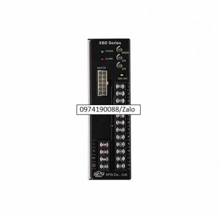
XBD120U
120W 200~230V 삼상 BLDC DRIVER
| Specification |
| Title |
Combi type |
XBA-620A-□ |
XBA-620B-□ |
XBA-620U-□ |
| Gear type |
XLM620G |
| D-Cut type |
XLM620D |
| Rated Output (continuous) |
W |
|
20 |
Rated Output
(continuous) |
|
Single Phase 100~120 |
Single Phase 200~230 |
Three Phase 200~230 |
|
|
50/60 |
|
|
0.65 |
0.40 |
0.20 |
|
|
1.30 |
0.90 |
0.50 |
| Rated TORQUE |
N·m(kgf·cm) |
0.066(0.66) |
| Driving TORQUE |
N·m(kgf·cm) |
0.08(0.8) |
Permissible Load
Inertia Moment |
J kg·m2 |
1.5×10-⁴ |
| GD2 kgf·㎠ |
6 |
| Rated RPM |
r/min |
3,000 |
| Speed Setting Range |
r/min |
200 to 3,000 (Speed Ratio 1:10) |
| Speed Variability Rate |
Load |
Less than ±1% (0 to rated torque, at rated speed) |
| Vlotage |
Less than ±1% (supply voltage ±10%, at rated speed with no load) |
| Temperture |
Less than ±1% (0 to +40℃ (+32 to +104℉), at rated speed with no load) |
|
|
|
|
|
※ For permissible load inertia in the geared motor, refer to Permissible Torque-Geared Motor [GD²].
※ Enter the ratio in the box(□) model number.
※ The values for each item is for the motor only. |
|
|
|
|
| □ Commonalities |
| Category |
Specifications |
| SLOW RUN / SLOW STOP |
0.5 to 15 seconds (Applicable for both Slow Run and Slow Stop) |
| Speed Control |
1. Built-in Potentiometer 2. External Potentiometer (20㏀ 1/4W) 3. External DC Voltage(0~5 Volt) |
| Input Signal |
Photocoupler input method, input resistance: 2㏀, operates at DC 12V±10%, common for EXT., CW, and CCW |
| Output Signal |
Opencollector output, external use conditions: Less than 26.4V 10mA, common for Speed Out and Alarm Out. |
| Protection Feature |
If following protection functions are operated, control unit alarm signal is outputs and motor comes to stop.
ㆍProtection for machine overload : When an overload that exceeds the motor’s rate touque has been continued for more than 5 seconds
ㆍProtection for overvoltage : When the voltage permitted for the control unit has exceed specified voltage
ㆍProtectionguard for image formation : When malfunction occures in the motor feedback signals due to cables disconnection and connector disconnection.
ㆍProtection for undervoltage : When the voltage permitted at the control unit has shortage of more than specified voltage
ㆍ Protection for over speeding : When the speed of the motor exceed 3800r/min |
| Motor Insulation Level |
Class E (120℃) |
| Time Rating |
Continuous |
|
|
| □ General Specs |
| Item |
MOTOR |
CONTROL UNIT |
| Dielectric strength |
If applying 60HZ 1,500V between the coil and the case for 1 minute after continuous operating under normal temperature and humidity conditions, any fault is not occurred |
Sufficient to withstand 3.0kV at 50Hz applied between power supply terminal (I/O terminal) And I/O terminals for 1 minutes, and 1.5kV at 50Hz applied between protective earth terminal and power supply terminals |
| Insulation Resistance |
After continuous operating under normal temperature and humidity conditions, if measured the resistance value between the coil and the case using DC500V Mega Tester, should be over 100㏁. |
If the resistance value between protection ground terminal and power input is measured using DC500V Mega Tester, should be over 100㏁. |
| Ambient Temperature |
℃ to +40℃(+32℉ to +104℉) (nofreezing) |
0℃ to +50℃(+32℉ to +122℉) (nofreezing) |
| Ambient Humidity |
Less then 85% (no dew condensation) |
| Ambience |
Nocorroive gas or dust |
| Protection Class |
IP65 (excluding the output shaft side) |
IP10 |
|
※ Caution: Use it, ensuring that surface temperature of motor does not exceed over 90℃. |
|
| □ Permissible Torque-Geared Motor [GD²] |
| Title |
Speed Setting Range [r/min] |
60~600 |
30~300 |
20~200 |
15~150 |
10~100 |
6~60 |
3~30 |
1.5~15 |
| Gear Ratio |
5 |
10 |
15 |
20 |
30 |
50 |
100 |
200 |
| XBA620( )-□K |
0.29
2.9 |
0.59
5.9 |
0.88
8.8 |
1.2
12 |
1.7
17 |
2.8
28 |
5.6
56 |
200
60 |
|
|
※ ( ) of item name represents voltage specification
※ □ of item name represents the reduction ratio.
※ Rotation direction is the same direction of additional motor marked in the ▩, others is reverse direction. |
|
| □ Permissible Load Inertia[J]- Geared Motor |
| Model |
Gear Ratio |
5 |
10 |
15 |
20 |
30 |
50 |
100 |
200 |
| XBA620( )-□K |
General run |
1.2×10-³
50 |
5×10-³
200 |
11×10-³
450 |
20×10-³
800 |
37×10-³
1.5×10³ |
92×10-³
3.7×10³ |
0.25
10×10³ |
0.5
20×10³ |
| Instant stop, run |
0.15×10-³
6.25 |
0.62×10-³
25 |
1.4×10-³
56 |
2.5×10-³
100 |
5.6×10-³
225 |
15.6×10-³
625 |
15.6×10-³
625 |
15.6×10-³
625 |
|
|
※ ( ) of item name represents voltage specification
※ □ of indicates deceleration ratio. |
|
| □ Permissible Overhand Load and Permissible Thrust Load |
| Model |
Gear Ratio |
Permissible Overhand Load |
Permissible Thrust Load |
| 10mm(0.3937 in) from end of the output shaft. |
20mm(0.7874 in) from end of the output shaft. |
| N |
kgf |
N |
kgf |
N |
kgf |
| Geared Motor |
XBA620( )-□K |
5 |
100 |
10 |
150 |
15 |
40 |
4 |
| 10~20 |
150 |
15 |
200 |
20 |
| 30~200 |
200 |
20 |
300 |
30 |
| Motor |
XBM620D |
87.2 |
8.72 |
107 |
10.7 |
|
|
※ ( ) of item name represents voltage specification
※ □ indicates deceleration ratio. |
Do not engage the thrust load. If unavoidable, engage below 50 % of motor weight. |
|
| □ RPM – Torque Feature |
| XBU620G( ) / XBU620D( ) |

|
|
|
XEAEW-1, XEAEW-2, XEAEW-3, XEAEW-5, XEAEW-7, XEAEW-10, XFD30, XFD50, XFD100, XFM630D, XFM630G, XFM850D, XFM850G, XFM9100D, XFM9100G, XFU630D, XFU630G, XFU850D, XFU850G, XFU9100D, XFU9100G,
XQU630GB, XQU860DB, XQU860DU, XQU860GB, XQU860GU, XQU975DB, XQU975DU, XQU975GB, XQU975GU, XQU912
XEAEW-1, XEAEW-2, XEAEW-3, XEAEW-5, XEAEW-7, XEAEW-10, XFD30, XFD50, XFD100, XFM630D, XFM630G, XFM850D, XFM850G, XFM9100D, XFM9100G, XFU630D, XFU630G, XFU850D, XFU850G, XFU9100D, XFU9100G,
XQU630GB, XQU860DB, XQU860DU, XQU860GB, XQU860GU, XQU975DB, XQU975DU, XQU975GB, XQU975GU, XQU912
XWM940D, XWM940D, XWM940G, XWM940G, XWD40A, XWD40B, XWU940GA, XWU940GB, XWU940DA, XWU940DB, XWD90A, XWD90B, XWD10A, XWD10BXWD25A, XWD25B,
XBD20A, XBD20B, XBD20U, XBD40A, XBD40B, XBD40U, XBD75A, XBD75B, XBD75U, XBD120A, XBD120B, XBD120U, XBD150A, XBD150B, XBD150U, XBD200B, XBD200U, XBD400U, XBD120U, XBD120U, XBD120U, XBD120U, XBD120U, XBD120U, XBD120U,

