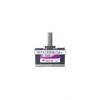
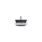
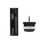
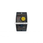
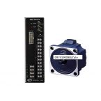
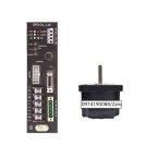
XWD25B
25W 200~230V BLDC Motor Control Unit
| Specification |
| Model |
Combi type |
XWA610A-□ |
XWA610B-□ |
| Gear type |
XWM610GB |
| D-Cut type |
XWM610BDB |
| Rated Output (continuous) |
W |
|
10 |
| Power Input |
|
Single Phase 100~120 |
Single Phase 200~330 |
|
|
50/60 |
|
|
0.6 |
0.35 |
|
|
0.8 |
0.5 |
| Rated TORQUE |
N·m(kgf·cm) |
0.05(0.5) |
| Driving TORQUE |
N·m(kgf·cm) |
0.06(0.6) |
Permissible Load
Inertia Moment |
J kg·m2 |
1.5×10-⁴ |
| GD2 kgf·㎠ |
6 |
| Rated RPM |
r/min |
2,000 |
| Speed Setting Range |
r/min |
200 to 2,000 (Speed Ratio 1:20) |
| Speed Variability Rate |
Load |
Less than ±1% (0 to rated torque, at rated speed) |
| Vlotage |
Less than ±1% (supply voltage ±10%, at rated speed with no load) |
| Temperture |
Less than ±1% (0 to +40℃ (+32 to +104℉), at rated speed with no load) |
|
|
|
|
|
※ Please reference No.5 Permissible Load Inertia Moment of Geared Motor |
|
|
|
|
| □ Commonalities |
| Category |
Specifications |
| SLOW RUN / SLOW STOP |
0.5 to 15 seconds (Applicable for both Slow Run and Slow Stop) |
| Speed Control |
1. Built-in Potentiometer 2. External Potentiometer (20㏀ 1/4W) 3. External DC Voltage(0~5 Volt) |
| Input Signal |
Photocoupler input method, input resistance: 2㏀, operates at DC 12V±10%, common for EXT., CW, and CCW |
| Output Signal |
Opencollector output, external use conditions: Less than 26.4V 10mA, common for Speed Out and Alarm Out. |
| Protection Feature |
If following protection functions are operated, control unit alarm signal is outputs and motor comes to stop.
ㆍProtection for machine overload : When an overload that exceeds the motor’s rate touque has been continued for more than 5 seconds
ㆍProtection for overvoltage : When the voltage permitted for the control unit has exceed specified voltage
ㆍProtectionguard for image formation : When malfunction occures in the motor feedback signals due to cables disconnection and connector disconnection.
ㆍProtection for undervoltage : When the voltage permitted at the control unit has shortage of more than specified voltage
ㆍ Protection for over speeding : When the speed of the motor exceed 3800r/min |
| Motor Insulation Level |
Class E (120℃) |
| Time Rating |
Continuous |
|
|
| □ General Specs |
| Item |
MOTOR |
CONTROL UNIT |
| Dielectric strength |
If applying 60HZ 1,500V between the coil and the case for 1 minute after continuous operating under normal temperature and humidity conditions, any fault is not occurred |
Sufficient to withstand 3.0kV at 50Hz applied between power supply terminal (I/O terminal) And I/O terminals for 1 minutes, and 1.5kV at 50Hz applied between protective earth terminal and power supply terminals |
| Insulation Resistance |
After continuous operating under normal temperature and humidity conditions, if measured the resistance value between the coil and the case using DC500V Mega Tester, should be over 100㏁. |
If the resistance value between protection ground terminal and power input is measured using DC500V Mega Tester, should be over 100㏁. |
| Ambient Temperature |
℃ to +40℃(+32℉ to +104℉) (nofreezing) |
0℃ to +50℃(+32℉ to +122℉) (nofreezing) |
| Ambient Humidity |
Less then 85% (no dew condensation) |
| Ambience |
Nocorroive gas or dust |
| Protection Class |
IP65 (excluding the output shaft side) |
IP10 (excluding the output shaft side) |
|
※ Caution: Use it, ensuring that surface temperature of motor does not exceed over 90℃. |
|
| □ Permissible Torque-Geared Motor [GD²] |
| Title |
Speed Setting Range [r/min] |
20~400 |
10~200 |
6.7~133 |
5~100 |
3.3~67 |
2~40 |
1~20 |
0.5~10 |
| Gear Ratio |
5 |
10 |
15 |
20 |
30 |
50 |
100 |
200 |
| XWA610( )-□K |
0.22
2.2 |
0.45
4.5 |
0.68
6.8 |
0.90
9.0 |
1.3
13 |
2.1
21 |
4.2
42 |
6.0
60.0 |
|
|
※ ( ) of item name represents voltage specification
※ □ of item name represents the reduction ratio.
※ Rotation direction is the same direction of additional motor marked in the ▩, others is reverse direction. |
|
| □ Permissible Load Inertia[J]- Geared Motor |
| Model |
5 |
10 |
15 |
20 |
30 |
50 |
100 |
200 |
| XWA610())-□K |
1.55
(6.2)
|
6.2
(24.8)
|
14
(56.0)
|
24.8
(99.2)
|
55.8
(223.2)
|
155
(620.0)
|
155
(620.0)
|
155
(620.0)
|
|
|
※ ( ) of item name represents voltage specification
※ □ of indicates deceleration ratio. |
|
| □ Permissible Overhand Load and Permissible Thrust Load |
| Model |
Gear Ratio |
Permissible Overhand Load |
Permissible Thrust Load |
| 10mm(0.3937 in) from end of the output shaft. |
20mm(0.7874 in) from end of the output shaft. |
| N |
kgf |
N |
kgf |
N |
kgf |
| Geared Motor |
XWA610())-□K |
5 |
100 |
10 |
150 |
15 |
40 |
4 |
| 10~20 |
150 |
15 |
200 |
20 |
| 30~200 |
200 |
20 |
300 |
30 |
| Motor |
XWM610D |
87.2 |
8.72 |
107 |
10.7 |
|
|
※ ( ) of item name represents voltage specification
※ □ indicates deceleration ratio. |
Do not engage the thrust load. If unavoidable, engage below 50 % of motor weight. |
|
| □ RPM – Torque Feature |
| XWU610G( ) / XWU610D( ) |

|
|
|
XTG95K, XTG810K, XTG915K, XTG920K, XTG930K, XTG950K, XTG9100K, XTG9200K, XTG105K, XTG1010K, XTG1015K, XTG1020K, XTG1030K, XTG1050K, XTG1010
XEAEW-1, XEAEW-2, XEAEW-3, XEAEW-5, XEAEW-7, XEAEW-10, XFD30, XFD50, XFD100, XFM630D, XFM630G, XFM850D, XFM850G, XFM9100D, XFM9100G, XFU630D, XFU630G, XFU850D, XFU850G, XFU9100D, XFU9100G,
XQU630GB, XQU860DB, XQU860DU, XQU860GB, XQU860GU, XQU975DB, XQU975DU, XQU975GB, XQU975GU, XQU912
XEAEW-1, XEAEW-2, XEAEW-3, XEAEW-5, XEAEW-7, XEAEW-10, XFD30, XFD50, XFD100, XFM630D, XFM630G, XFM850D, XFM850G, XFM9100D, XFM9100G, XFU630D, XFU630G, XFU850D, XFU850G, XFU9100D, XFU9100G,
XQU630GB, XQU860DB, XQU860DU, XQU860GB, XQU860GU, XQU975DB, XQU975DU, XQU975GB, XQU975GU, XQU912
XWM940D, XWM940D, XWM940G, XWM940G, XWD40A, XWD40B, XWU940GA, XWU940GB, XWU940DA, XWU940DB, XWD90A, XWD90B, XWD10A, XWD10BXWD25A, XWD25B, XWD25B, XWD25B, XWD25B, XWD25B, XWD25B, XWD25B, XWD25B,


