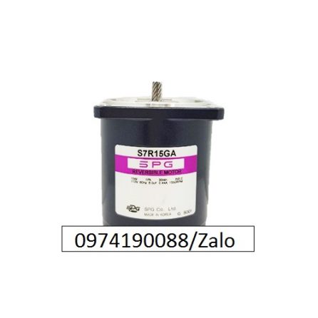
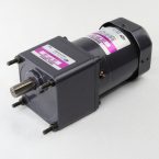
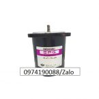
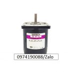
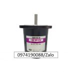
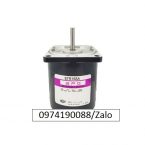
S7R15GA
15W 110V REVERSIBLE GEAR MOTOR
| □ Specification |
SIZE
mm sq. |
Type |
Pole |
Output |
Voltage |
Fre. |
Duty |
Rated Load |
Starting Torque |
Capacitor |
| Current |
Speed |
Torque |
| (W) |
(V) |
(Hz) |
(A) |
(rpm) |
(kg-cm) |
(N-m) |
(kg-cm) |
(N-m) |
(uF) |
|
70
|
S7R15GA
S7R15GA(T/P)
S7R15GACE |
4 |
15 |
1 ø 110 |
60 |
30min. |
0.44 |
1600 |
1.00 |
0.100 |
1.10 |
0.110 |
6.0 |
S7R15GB
S7R15GB(T/P)
S7R15GBCE |
4 |
15 |
1 ø 220 |
60 |
30min. |
0.22 |
1550 |
1.00 |
0.100 |
1.10 |
0.110 |
1.5 |
S7R15GC
S7R15GC(T/P)
S7R15GCCE |
4 |
15 |
1 ø 100 |
50 |
30min. |
0.42 |
1250 |
1.25 |
0.125 |
0.90 |
0.090 |
6.0 |
| 60 |
0.42 |
1550 |
1.00 |
0.100 |
S7R15GD
S7R15GD(T/P)
S7R15GDCE |
4 |
15 |
1 ø 200 |
50 |
30min. |
0.21 |
1200 |
1.25 |
0.125 |
0.90 |
0.090 |
1.5 |
| 60 |
0.21 |
1500 |
1.00 |
0.100 |
S7R15GE
S7R15GECE |
4 |
15 |
1 ø 100 |
50 |
30min. |
0.37 |
1200 |
1.25 |
0.125 |
0.95 |
0.095 |
6.0 |
| 60 |
0.41 |
1550 |
1.00 |
0.100 |
| 1 ø 115 |
60 |
0.35 |
1600 |
1.00 |
0.100 |
4.5 |
S7R15GX
S7R15GXCE |
4 |
15 |
1 ø 220 |
50 |
30min. |
0.17 |
1200 |
1.25 |
0.125 |
0.90 |
0.090 |
1.2 |
| 1 ø 240 |
0.18 |
1.45 |
0.145 |
1.10 |
0.110 |
|
|
|
|
– S7R15GE is UL approved (UL FILE No. E172720) thermally protected type.
– Please use appropriate capacitors according to the using voltage for S7R15GE type since the size of the capacitors differ to the different voltages and when not used properly, it may cause malfunction. Please inform required voltage when ordering or capacitor for 115V will be delivered.
– “CE” marked at the end of the model name indicates that it is impedance protected type which has received CE(Rile No. E9766002E01, Certificate Institute : TÜV Rheinland) with built-in TP S7R15GECE is available only for 115V specification.
-“TP”marked at the end of the model name indicates that it is standard motor with Thermal Protector mounted. S7R15GE, S7R15GX is thermally protected type with TP mounted.
– Data is measured with friction brake mounted.
– There is not marked the ‘L’ type caused by exclusive use. |
|
|
|
|
| ■ 50Hz |
| Model |
Gear Ratio |
3 |
3.6 |
5 |
6 |
7.5 |
9 |
10 |
12.5 |
15 |
18 |
20 |
25 |
30 |
| rpm |
500 |
416 |
300 |
250 |
200 |
166 |
150 |
120 |
100 |
83 |
75 |
60 |
50 |
| S7KA□B |
kg-cm |
3.2 |
3.9 |
5.4 |
6.5 |
8.1 |
9.7 |
10.8 |
13.5 |
16.2 |
19.4 |
19.8 |
24.2 |
29.1 |
| N-m |
0.314 |
0.382 |
0.530 |
0.637 |
0.794 |
0.951 |
1.059 |
1.324 |
1.587 |
1.902 |
1.912 |
2.373 |
2.854 |
|
|
| Model |
Gear Ratio |
36 |
40 |
50 |
60 |
75 |
90 |
100 |
120 |
150 |
180 |
200 |
|
|
| rpm |
41 |
37 |
30 |
25 |
20 |
16 |
15 |
12 |
10 |
8 |
7.5 |
|
|
| S7KA□B |
kg-cm |
34.9 |
38.8 |
43.6 |
50.0 |
50.0 |
50.0 |
50.0 |
50.0 |
50.0 |
50.0 |
50.0 |
|
|
| N-m |
3.423 |
3.805 |
4.276 |
4.900 |
4.900 |
4.900 |
4.900 |
4.900 |
4.900 |
4.900 |
4.900 |
|
|
|
|
| ■ 60Hz |
| Model |
Gear Ratio |
3 |
3.6 |
5 |
6 |
7.5 |
9 |
10 |
12.5 |
15 |
18 |
20 |
25 |
30 |
| rpm |
600 |
500 |
360 |
300 |
240 |
200 |
180 |
144 |
120 |
100 |
90 |
72 |
60 |
| S7KA□B |
kg-cm |
3.0 |
3.6 |
5.1 |
6.1 |
7.6 |
9.1 |
10.1 |
12.7 |
15.2 |
18.2 |
18.7 |
22.8 |
27.3 |
| N-m |
0.294 |
0.353 |
0.500 |
0.598 |
0.2745 |
0.892 |
0.990 |
1.245 |
1.491 |
1.785 |
1.795 |
2.236 |
2.677 |
|
|
| Model |
Gear Ratio |
36 |
40 |
50 |
60 |
75 |
90 |
100 |
120 |
150 |
180 |
200 |
|
|
| rpm |
50 |
45 |
36 |
30 |
24 |
20 |
18 |
15 |
12 |
10 |
9 |
|
|
| S7KA□B |
kg-cm |
32.8 |
36.5 |
41.0 |
49.2 |
50.0 |
50.0 |
50.0 |
50.0 |
50.0 |
50.0 |
50.0 |
|
|
| N-m |
3.217 |
3.579 |
4.021 |
4.825 |
4.900 |
4.900 |
4.900 |
4.900 |
4.900 |
4.900 |
4.900 |
|
|
|
|
|
|
– The code in □of gearhead model is for gear ratio.
– It is the permissible torque of the assembled motor and gearhead.
– The permissible torque of the assembled with motor and inter-decimal gearhead is 50Kg-cm.
– ■color indicates that the output shaft of the geard motor rotates in the same direction as the output shaft of the motor. Others indicate rotation in the opposite direction.
– Rotational speed based on synchronous speed (50Hz : 1500rpm, 60Hz : 1800rpm) divided by gear ratio. The actual rotation speed is less 2-20% than the displayed value according to the load.
– There is no marked the ‘L’ type caused by exclusive use. |
|
|
| □ Dimensions |
 |
|
| □ Schematic Diagrams |
| The direction of motor rotation is as viewed from the front shaft end of the motor. |
|
|
S7R15GA S7R15GB
S7R15GC S7R15GD
|
S7R15GX
S7R15GXCE
|
| CW , CCW |
CW , CCW |
 |
 |
|
|
|
S7R15GA(T/P) S7R15GB(T/P)
S7R15GC(T/P) S7R15GD(T/P)
S7R15GACE S7R15GBCE S7R15GE
S7R15GCCE S7R15GDCE S7R15GECE
|
| CW, CCW |
 |
|
|
|
|
S7R15GA, S7R15GA(T/P), S7R15GACE, S7R15GB, S7R15GB(T/P), S7R15GBCE, S7R15GC, S7R15GC(T/P), S7R15GCCE, S7R15GD, S7R15GD(T/P), S7R15GDCE, S7R15GE, S7R15GECE, S7R15GX, S7R15GXCE, S7R15GA , S7R15GC , S7R15GB, S7R15GX, S7R15GXCE, S7R15GA(T/P) , S7R15GC(T/P) , S7R15GACE , S7R15GCCE , S7R15GB(T/P), S7R15GD(T/P), S7R15GE, S7R15GBCE , S7R15GECE, S7R15GDCE , S7I15GA, S7I15DA, S7I15GB,S7I15DB, S7I15GXCE, S7I15DXCE, S7I15GA-S12, S7I15GB-S12, S7I15GX-S12CE, S7I15GA-V12, S7I15GB-V12, S7I15GX-V12CE, S7I15GT,
S7R15GA-E,S7R15GB-E,S7R15GX-ECE,S7I15GA-T,S7I15GB-T,S7I15GX-TCE,S7R15GA-ES12,S7R15GB-ES12,S7R15GX-ES12CE,SUA715B-V12,SRB02

